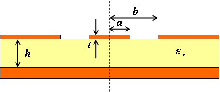
Grounded Coplanar Waveguide (G-CPW)
or Conductor-Backed Coplanar Waveguide (CB-CPW)
2010.10.30 Takuichi Hirano

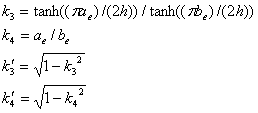
 ([2] or
Eq.(3.10) in [3])
 ([2] or
Eq.(3.10) in [3])
 (Eq.(8)
in [1])
 (Eq.(9b)
in [1])
where, K(m) is the complete elliptic integral of the first kind.
 (Eq.(9a)
in [1])
 (Eq.(10)
in [1])

References
- G. Ghione, C.U. Naldi, "Coplanar Waveguides for MMIC Applications:
Effect of Upper Shielding, Conductor Backing, Finite-Extent Ground Planes,
and Line-to-Line Coupling," IEEE Transactions on Microwave Theory and
Techniques, Vol.35, No.3, pp.260-267, March 1987.
- Y.-C. Shih, "Broadband characterization of conductor-backed coplanar
waveguide using accurate on-wafer measurement techniques" Microwave J.,
Vol.34, No.4, pp.95-105, April 1991.
- R.N. Simons: Coplanar Waveguide Circuits, Components, and Systems, Wiley-IEEE
Press, 2001.
Appendix
Download Mathematica Notebook File: cbcpw.nb (43KB)
Copyright(c) 2010 Takuichi Hirano
Back


![]() ([2] or
Eq.(3.10) in [3])
([2] or
Eq.(3.10) in [3])![]() ([2] or
Eq.(3.10) in [3])
([2] or
Eq.(3.10) in [3]) (Eq.(8)
in [1])
 (Eq.(9b)
in [1])
(Eq.(9b)
in [1])![]() (Eq.(9a)
in [1])
(Eq.(9a)
in [1]) (Eq.(10)
in [1])